Basic DC Electronics Concepts
| Published: |
| Last edit: |
Introduction
I recently got back into electronics after quite a long time, due to getting interested in custom split keyboards, and buying some microcontrollers and components. It turns out I remember a fair bit and had forgotten a similar amount. So, in an effort so reduce the time it takes to get back the familiarity and intuitiveness I once had, I’m writing it (almost) all down here. I hope at some point I will have a similar article on AC as well.
Back to everyday basics
In this section I aim to provide a quick refresher of the most common and basic concepts when it comes to DC electric circuits.
Current1
First question to answer is “What is electric current?” since that’s the most common concept you will have heard of. In the simplest terms electric current ($$inline-mathsI$$) is the movement of charge ($$inline-mathsQ$$) through a medium such as a copper wire, and it is measured in $$inline-mathsamperes$$ ($$inline-mathsA$$). You can think of this as the flow rate of water through a pipe, the higher the amps, the more water flows through in the same amount of time.
Voltage2
The next most common concept you will have heard of is “voltage” or “volts”, so lets try to answer what that is. $$inline-mathsVolts$$ ($$inline-mathsV$$) are a unit of measurement of the electric potential differential between 2 points. $$inline-mathsVoltage$$ ($$inline-mathsV$$ or $$inline-mathsU$$) refers to that potential difference. You can think about it as the pressure difference of 2 points in a pipe. The higher the voltage, the more pressure there is at one point compared to the other.
Ground3
A closely related concept to this is the “ground” or “earth”. This is usually a reference point from which to measure voltages in the system, $$inline-mathsV_{ground}=0$$ always, but it may also be an electrical connection to a neutral node that has a lot of available charges. In the water-pipes analogy we have been using think of it as the sea/ocean.
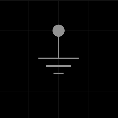
Figure 1: Electrical symbol for ground
Power4
Another common concept you will have heard of is “power” or “wattage” ($$inline-mathsP$$). This is the rate of transfer of electrical energy, it is equal to the current multiplied by the potential differential ($$inline-mathsP=I\cdot{}V$$), and it is measured in $$inline-mathswatts$$ ($$inline-mathsW$$). Using the water-pipes analogy again, this measures how much “work” could be done with a given water pressure and flow rate, akin to hydraulic systems.5
Resistance6
Lastly, the not-so-common concept I will introduce here is the “resistance” ($$inline-mathsR$$) which is measured in $$inline-mathsohms$$ ($$inline-maths\Omega$$). As the names suggests this is the resistance that a charge encounters when trying to move.
Ohm’s law
This is probably the most important thing in this article, and if you ever remember anything from it, let it be this:
What this is saying, using the water and pipes analogy from above, is that the difference in pressure between 2 points is equal to the flow rate times the resistance to the water moving, which I hope it makes intuitive sense now, since the harder it is to push the water (high resistance) the more pressure you will need to maintain the same flow rate.
Components
This is probably going to be the longest part of the article as I will try and go though common components and describe them in an intuitive way. This list is not exhaustive.
Wires
Possibly the simplest component, an ideal wire has no resistance and is used to connect other components together. In reality every wire has some resistance dependent on the material and area, but for most applications this resistance can be ignored.
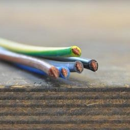
Fig 2.a:
Electrical wires
Fig 2.b:
Electric symbol for wire
Figure 2: Wires
Constant current sources
As the name suggests these sources provide a constant current to the circuit regardless of load (resistance). Thus the voltage at the terminals can vary depending on the resistance.
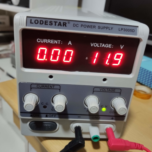
Fig 3.a:
Bench top power supply. (C.C symbol on the left is for constant current)
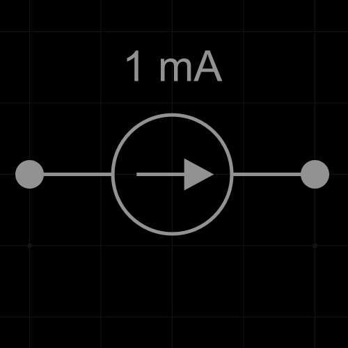
Fig 3.b:
Electric symbol for constant current source
Figure 3: Constant current source
Constant voltage sources
As the name suggests these sources provide a voltage current to the circuit regardless of load (resistance). Thus the current inside the circuit can vary depending on the resistance.
Fig 4.a:
Bench top power supply. (C.V symbol on the right is for constant voltage)
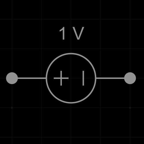
Fig 4.b:
Electric symbol for constant voltage source
Figure 4: Constant voltage source
Batteries
For the most part batteries can be thought of as constant voltage sources. In reality the voltage of a battery depends on its charge level and decreases as the battery is being used. Thus even a relatively charged battery may not produce it’s printed voltage value.
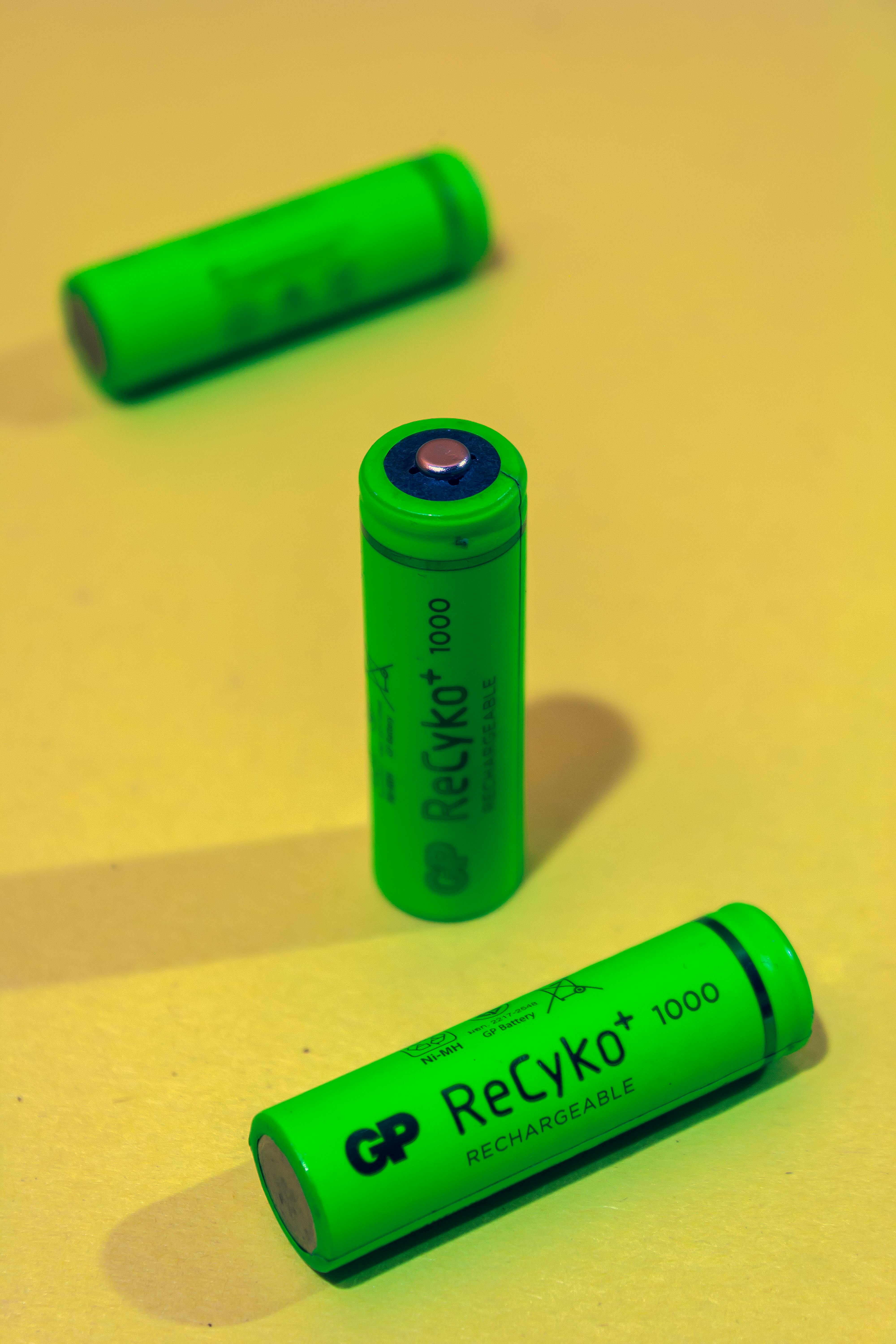
Figure 5: Batteries
Resistors
These are the next simplest passive component in a circuit, their role is usually to reduce the current flowing through the circuit in order to protect more delicate components. They do this by resisting the flow of current. They consume some energy that is converted to heat.
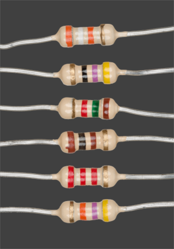
Fig 6a:
Image of axial-lead resistors of varying resistance
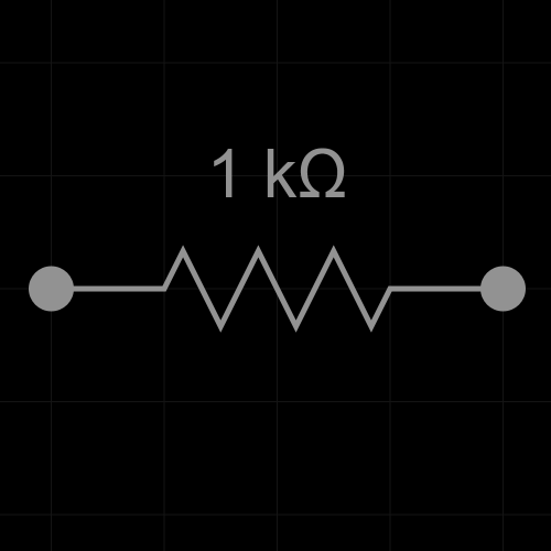
Fig 6.b:
Electric symbol for fixed resistor
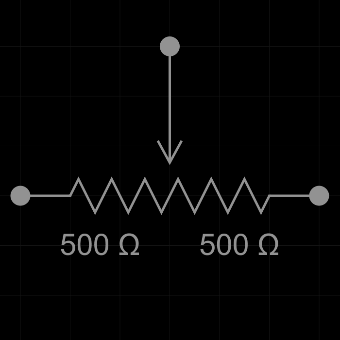
Fig 6.c:
Electric symbol for variable resistor
Figure 6: Resistors
Equivalent resistance
- When 2+ resistors are on the same wire, connected one after the other, their equivalent resistance is the sum of their individual resistances. (Series)
- When 2+ resistors are connected to the same 2 points then their inverse resistance is equal to the sum of the inverse of each individual resistance. (Parallel)
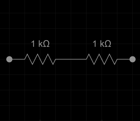
Fig 7a:
Image of fixed resistors connected in series
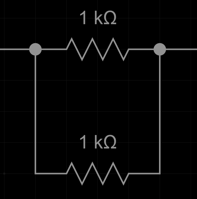
Fig 7.b:
Image of fixed resistors connected in parallel
Figure 7: Series and parallel resistors
Switches/Buttons
The role of these components is to switch the path that current flows through. They can also be used to fully disconnect part of the system.
Buttons are a special kind of switches that are normally “off” which means that by default no current flows through them.
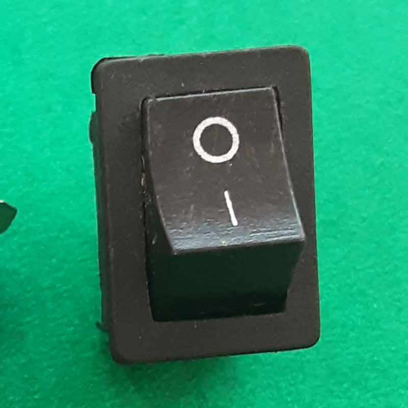
Fig 8.a:
Image of a switch
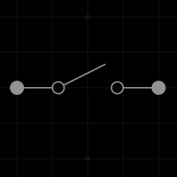
Fig 8.b:
Electric symbol for a switch
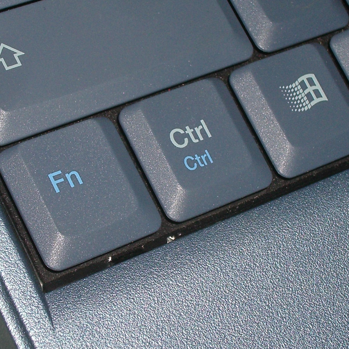
Fig 8.c:
Image of a button
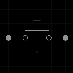
Fig 8.d:
Electric symbol for a button
Figure 8: Switches and buttons
Fuses
An ideal fuse behaves like an ideal wire ($$inline-mathsR=0$$) until it reaches its limit at which point it should act as a perfect insulator ($$inline-mathsR=\infty$$). They are useful for protecting circuits from current surges that would damage expensive components or cause injuries (e.g. fires).
Most common ones I have encountered are a made from a piece of conductive material, encased in either glass or ceramic, with a specific resistance such that it will fail (melt/burn) when the current exceeds the safe value.
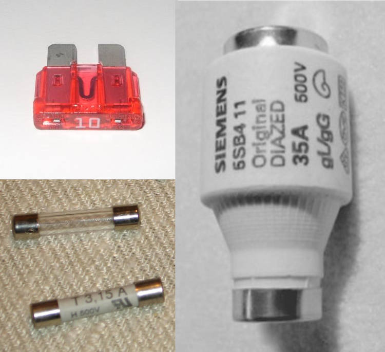
Fig 9.a:
Image of different types of fuses
Fig 9.b:
Electric symbol for a fuse
Figure 9: Fuses
Traditional Light bulbs
Traditional light bulbs are very close in construction to the latter fuses I described. They work by passing current through a wire that heats up enough to generate light. This filament is then encased in a glass bulb and put under vacuum or filled with some other inert gas to prevent the filament from catching fire/oxidizing due to the high temperatures.
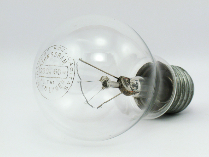
Fig 10.a:
Image of an incandescent light bulb
Fig 10.b:
Electric symbol for a light bulb
Figure 10: Fuses
Diodes
These components are used to keep the flow of current in only one direction. An ideal diode behaves like an ideal wire when current passes in the forward direction ($$inline-mathsR_{forward}=0$$), and as a perfect insulator when current tries to pass in the opposite direction ($$inline-mathsR_{backward}=\infty$$). In reality there is some internal resistance for the forward direction, and there is a current at which the diode will start to allow current in the opposite direction.
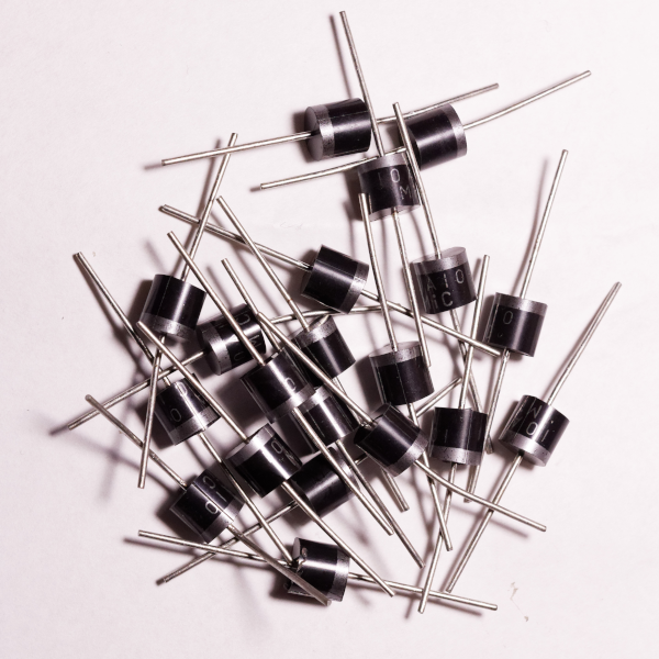
Fig 11.a:
Image of a pile of diodes
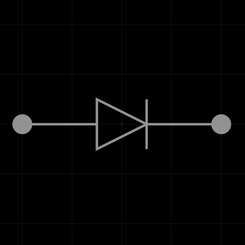
Fig 11.b:
Electric symbol for a diode
Figure 11: Diodes
LEDs
Probably the most common type of light recently, name “LED” stands for “light emitting diode”. As the name suggests these are diodes that also emit light, as such, unlike the traditional light bulbs, they have a concept of “forward direction” for the current and will not work otherwise. Another difference is that they do not emit light due to black-body radiation7 (heat).
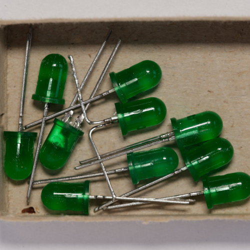
Fig 12.a:
Image of a pile of green LEDs
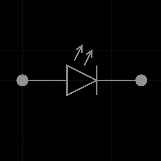
Fig 12.b:
Electric symbol for a LED
Figure 12: LEDs (Light Emitting Diodes)
Capacitors
A capacitor is a device that stores electrical energy by accumulating electric charges. This is usually done by having 2 electric conductor surfaces, that store the charges, close together separated by an insulator. A capacitor is characterized by a constant $$inline-mathscapacitance$$8 ($$inline-mathsC$$) measured in $$inline-mathsfarads$$ ($$inline-mathsF$$), defined as the ratio of charge ($$inline-mathsQ$$) on each conductor surface to the voltage ($$inline-mathsV$$) between them. The accumulation of these charges is a direct consequence of the voltage.
When a capacitor is disconnected from a live circuit the charge stored in it will persist, that is why it is advised to discharge capacitors manually before working on circuits.
Be careful when connecting a capacitor to a closed circuit! Because the charge accumulated by the capacitor is only there due to the previous voltage, when connected to a closed circuit the capacitor will have am equal voltage between its leads, which can lead to current spikes though the circuit.
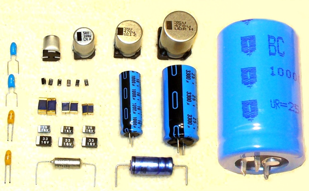
Fig 13.a:
Image of different types of capacitors
Fig 13.b:
Electric symbol for a capacitor
Figure 13: Capacitors
Inductors
An inductor is a component that stores energy in a magnetic field when an electric current flows through it. An inductor typically consists of an insulated wire wound into a coil. An inductor is characterized by its $$inline-mathsinductance$$9 ($$inline-mathsL$$), which I don’t understand well enough to explain it here yet.
The most important thing to remember though is that inductors oppose any changes in current through them. Which means we should be careful when disconnecting them because that can lead to spiking voltages and electric arcs.
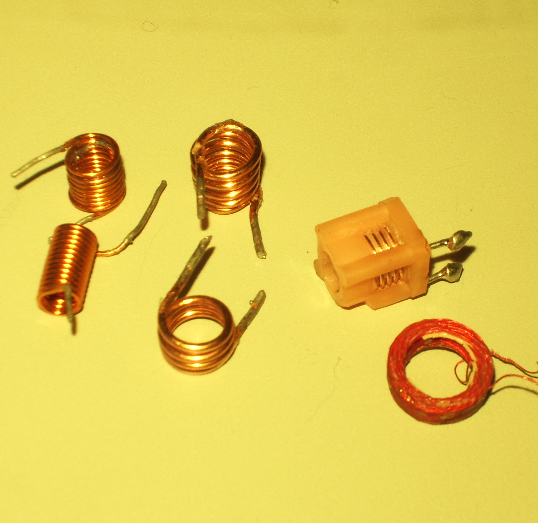
Fig 14.a:
Image of different types of inductors (coils)
Fig 14.b:
Electric symbol for a inductor
Figure 14: Inductors
Transistors
Transistors can be thought of as switches that are controlled by current or voltage. They usually have 3 leads/wires coming out of them: base/gate, source/collector, drain/emitter. The gate as the name suggests controls the current that flows between the collector and emitter. Usually small changes in the gate’s input result in bigger changes to the current between the collector and emitter, so they can be used for amplification as well.
BJTs
BJT stands for “bipolar junction transistor” and it uses a small current between the base and emitter terminals to control a higher current between the collector and emitter terminals.
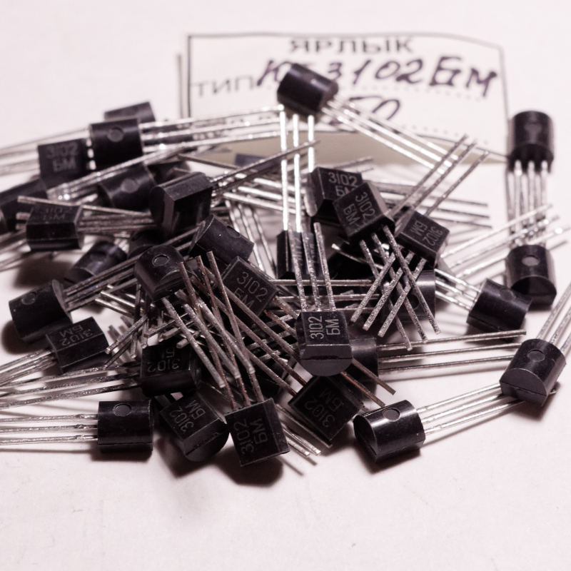
Fig 15.a:
Image of a pile of KT3102 BJTs
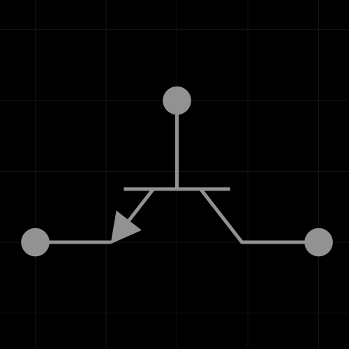
Fig 15.b:
Electric symbol for a NPN BJT
Figure 15: BJT
FETs
FET stans for “field-effect transistor” and it uses a voltage between the gate and source to control the current between the source and drain. The advantage of FETs is that no current has to go through the gate for it to be controlled. MOSFETs are special type of FET with the further advantage that the circuit behind the gate can be isolated from the high current between the source and drain.
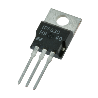
Fig 16.a:
Image of IRF630 MOSFET
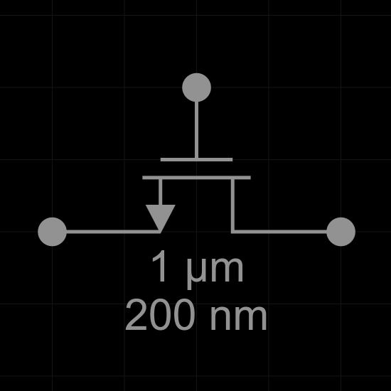
Fig 16.b:
Electric symbol for a n-channel FET
Figure 16: FETs
Relay
A relay is an electrically operated mechanical switch, usually used for high current applications where full isolation of the control circuit is required. They are usually comprised of an electromagnet that closes or opens the controlled circuit.
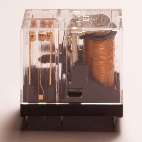
Fig 17.a:
Image of a relay
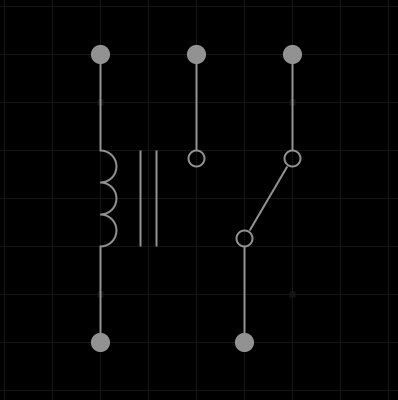
Fig 17.b:
Electric symbol for a switching relay
Figure 17: Relays